Lab 6: The Internet of Things and Serial Peripheral Interface
Number of Hours Spent on Lab: 20 hours
Main Goals
The main goal of this lab was to implement the SPI functionality of the MCU and interface with a temperature over an SPI link. The ESP8266 was also interfaced with the MCU over a UART link to toggle an LED on the board and display the output of the temperature sensor. These results were written on an HTML page, and allows the user to update the resolution of the temperature data displayed. Finally, a logic analyzer functionality on the oscilloscope was used to help measure outputs of the SPI data communication, and assist in any debugging.
Design Approach
SPI Design
In order to design the code for the SPI, it first needed to be initialized on the MCU. The SPI’s baud rate was set to 625 kHz in order to run slower than the clock of the temperature sensor. In addition, the data size for the communication was set to 8 bits in order to align with the data output of the sensor.
A separate function was then created to transmit a byte over SPI and return its received character. This would write 8 bits of data to the data register when the transmit buffer register is empty, and return its received character when the receive buffer is no longer empty.
When using SPI for the temperature sensor, it would be configured to a specific resolution based on the user input from the HTML webpage. The chip enable for the sensor was set to a GPIO output pin that would be toggled on only when SPI was transmitting data and off otherwise. Two SPI function calls were used for each read and write of the temperature sensor. When writing data, the call would first go to the write address of the temperature sensor, and then followed with the configuration information that includes the desired resolution. There were two different times needed for reading the data bits. This is because the read data from the temperature sensor is 16 bits, so it was split up into two 8-bit read calls for the MSB and LSB. Some conversion was then performed on these bits to properly display the temperature as a positive or negative number.
HTML Web Page Design
The HTML web page contained two separate forms. One to toggle the LED on and off, and the other to determine the resolution of the temperature sensor. Depending on what the person selects, the resolution of the temperature output would update on the webpage. The information given to the webpage would interact with the ESP8266 in order to wirelessly connect with the MCU code by using GET requests.
Circuit Design
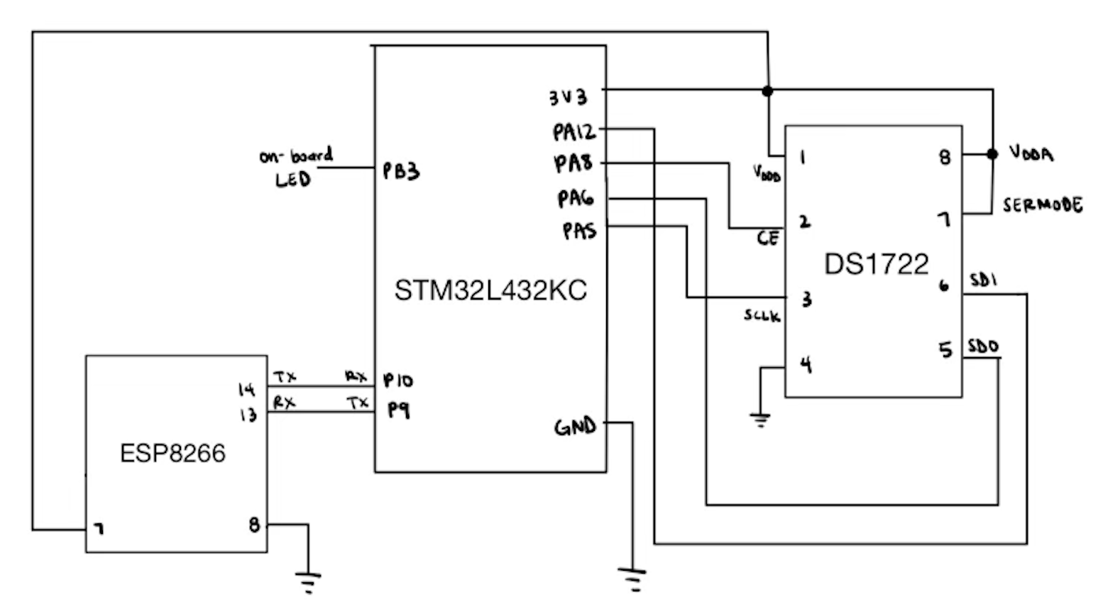
The circuit created consisted of an MCU, ESP8266, and DS1722 Digital Thermometer.
Pin Assignment
| variable | pin # |
|---|---|
| SCLK | A5 |
| MISO | A6 |
| CSS | A8 |
| TX | A9 |
| RX | A10 |
| MOSI | A12 |
| LED | B3 |

Testing Approach
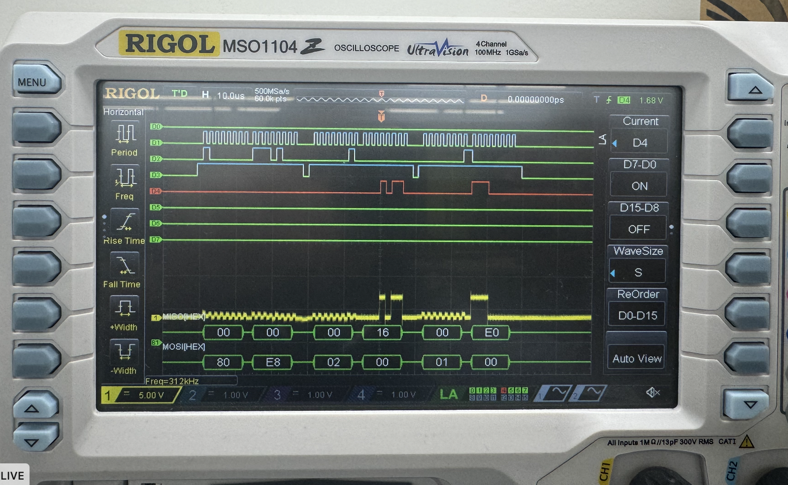
In order to test the design, I used both the logical analyzer and debugger window. I used the logic analyzer to check if a clock signal, chip select, and the MISO and MOSI lines were sending a signal. I then checked what the values were of the MISO line to see if the value being being read seemed reasonable to the room temperature. I then used my finger to touch the sensor, and check if the temperature reading would increase when my finger was touching it and decrease when I released my finger. As you can see in the image below, the MISO line reads 16 in Hex which equals 22 degrees Celsius. This is a reasonable tempearture to be recording since it is about room temperature.

I then used the debugger window to print the values that were read from the temperature sensor to see if they were properly converted into integer values of the correct resolution.
Design Requirements
After testing the design on the oscilloscope and in real-life, I can confirm the design meets all specs.