Lab 4: Digital Audio
Number of Hours Spent on Lab: 20 hours
Main Goals
The main goals of this lab was to drive a speaker from the MCU by enabling the I/O pins. In order to do so, the timer functionality needed to be implemented in order to create a square wave at the desired frequency/pitch and also indicate how long each note should be played for. Finally, a library from C needed to be written from scratch for the Timer to be implemented, which required getting familiar with the datasheet.
Design Approach
Delay Duration Design
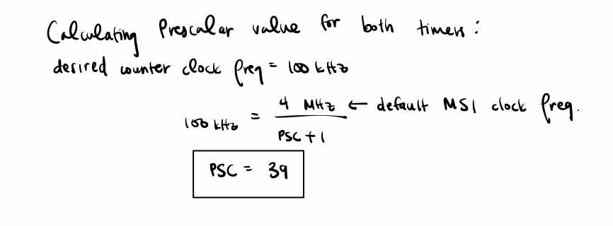
In order to design the code for the delay, there were 2 functions written. One function intialized the delay timer, while the other function would use a timer to delay the code to the desired number of milliseconds. The value of the prescalar was sent to 39 in order to get a counting clock frequency of 100 kHz since the system’s clock is at 4 MHz when it is set to the default MSI. The counter was also enabled and set to 0 during initialization.

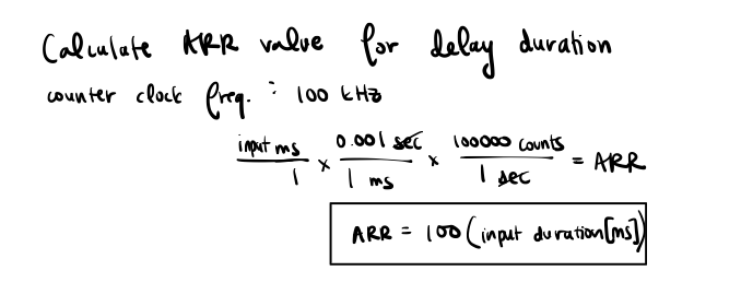
Next, the delay function took in a pointer to a timer along with the desired delay time. This function first set the auto-reload register to 100*input delay in order to get the desired maximum counting value before resetting when the counting clock frequency is at 100 kHz. Next, the Counter and Capture/Compare 1 Interrupt flag values were set to 0. A while loop was then created to keep running until the Capture/Compare Interrupt flag is turned on, which is when the counter has a greater value than the ARR register.

Using the equations for the arr value, the maximum and minimum delay values could be found by using the maximum and minimum values that the auto-reload register could hold.


Pulse Width Modulator Design
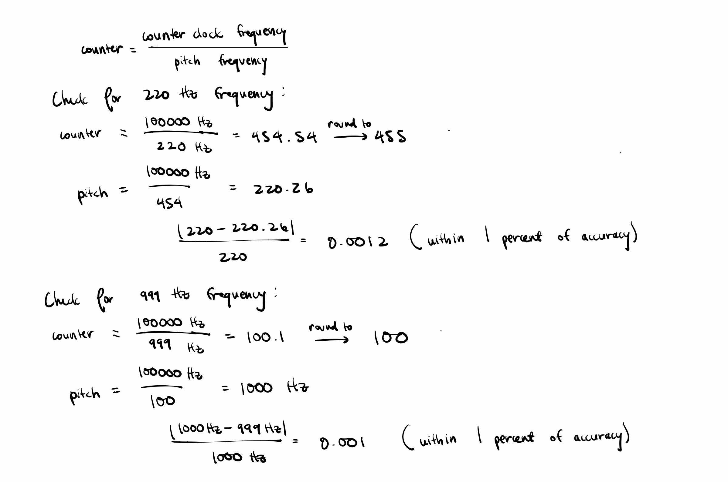
The PWM design consisted of a function that initialized the PWM timer and a function that produced a square wave at the desired frequency. In the initialization funtion, the prescalar was also set to 39 in order to get a counting clock frequency of 100 kHz. The 100 kHz counter clock frequency ensured that our pitch output would remain within 1 percent of the desired pitch for frequencies between 220 and 1000 Hz.

In addition, the auto-reload preload enable was set so that the ARR register is buffered. The Output Compare 1 Mode bits were set also set so that the PWM mode is set. The Capture Compare 1 Output enable and the Main Output Enable were also turned on so. Finally, the update generation was set so that the counter is reinitialized and the registers are updated. Lastly, the counter is then enabled for the timer. The output of this function was set to an alternate function in order to connect the timer value with the GPIO pins.
For the setPitch function, the ARR register was set to 100000/inputfrequency in order to get the desired number of counts for one period of the square wave. Knowing the maximum and minimum ARR values along wtih its relationship to the input frequency, the maximum and minimum frequency ranges can be calculated.


The update generation was set so that the counter is reinitialized and the registers are updated. Lastly, the counter is then enabled for the timer.
Circuit Design
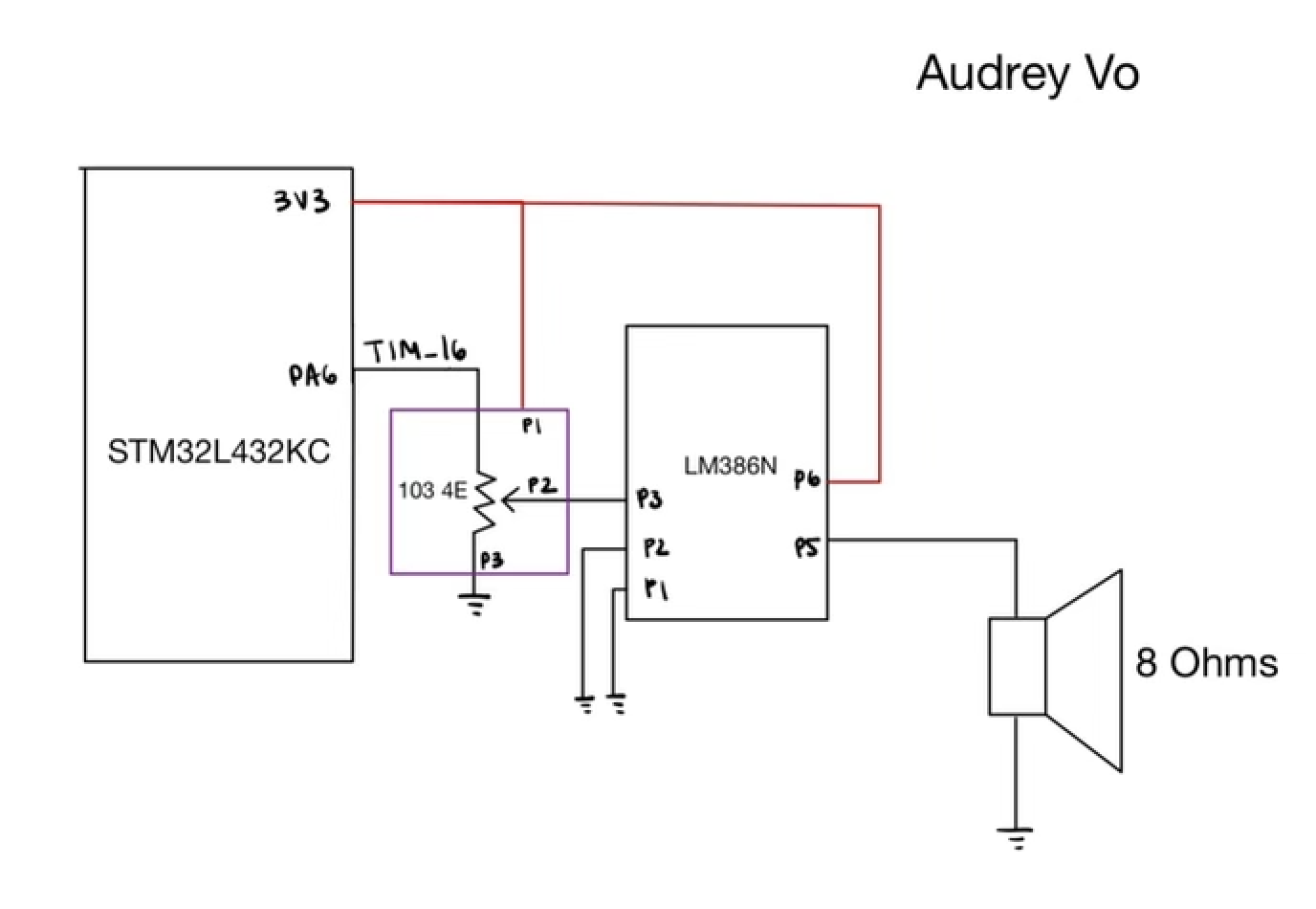
The circuit created consisted of a 10k potentiometer that took in the output of the PWM output and inputted the voltage drop into the LM386N amplifier. The LM386N was configured so that no gain was used, and its output was fed into the an 8 Ohm speaker. This configuration allowed for the volume to be controlled by adjusting the potentiometer and to limit current drawn from the GPIO pins.
Pin Assignment
| variable | pin # |
|---|---|
| TIM16 | A6 |
| TIM15 | A9 |

Finished Lab
Testing Approach
In order to test the design, I used an oscilloscope to measure the frequency of the output pitch and the output delay. If the delay was set to 10 ms, the frequency output is expected to be 50 Hz. Using the oscilloscope, this was the value I measured. For the output frequency, I set the pitch to a value of 250 Hz, and measured the output of the timer pin. As expected, I saw a value at about 248 Hz, which matches very closely to the 250 Hz. Thus, my circuit worked as desired.
Design Requirements
After testing the design on the oscilloscope and in real-life, I can confirm the design meets all specs.